Hinge Play and Hinge Wear
(2-26-2014-update)
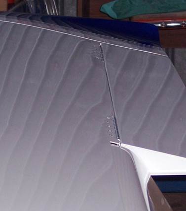
My first set of stock MS hinges did not
last very long. The inherent play
combined with the torsional vibration produced by the engine caused the aileron
hinges to get hammered by bouncing ailerons.
Note that this is not related to flutter. The entire mass balanced aileron would move
vertically as the wing responded to the power pulses of the engine. Over time, the aluminum hinge holes were
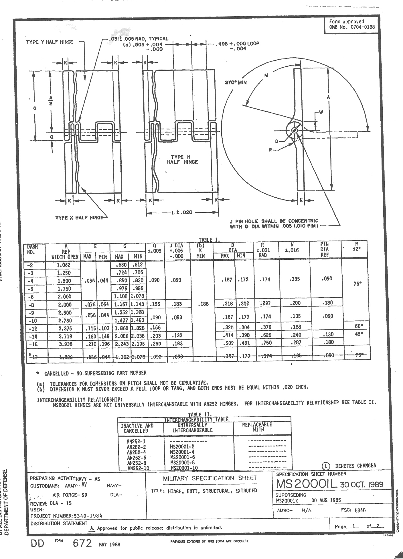
elongated vertically. A review of the
MS20001 hinge specification reveals an allowable ID of .093 to .098" for the hinges we are using on the
Lancair. The MS hinge pin is .089 +/-.001. Given this range, one is guaranteed
lots of play.
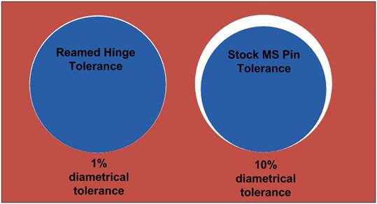
Figure 1, Graphic Representation of Tolerance
Difference
As the OD of the
pin and the ID of the hinge spread,
local stresses rise, wear rates climb very rapidly and, in a vibration environment, the hinge gets hammered by the mass
of whatever is attached to the other side. Going the
other direction, as you approach a perfect line to line fit, loads are distributed and the relative motion between the
hinge halves vanishes, eliminating the hammering,
play and wear. The MS20001, per
its specification, is simply poorly suited for applications where a close tolerance hinge is desired. The above figure graphically shows the
magnitude of the difference.
I began
investigating alternatives that would eliminate both play and wear.
Over time, three options were examined:
1.
Sleeved Teflon Pins
(Gary Hall kit)
2.
Carbinge
3.
Reamed Aluminum MS
Hinge with a larger Stainless Steel Pin
The following clip compares four types of hinge material in
new condition: MS hinge with an MS pin,
MS hinge with the Teflon sleeved pin, Carbinge, and reamed MS hinge with
welding wire.
Four Hinge Type
Comparison Video
Reamed MS Hinge
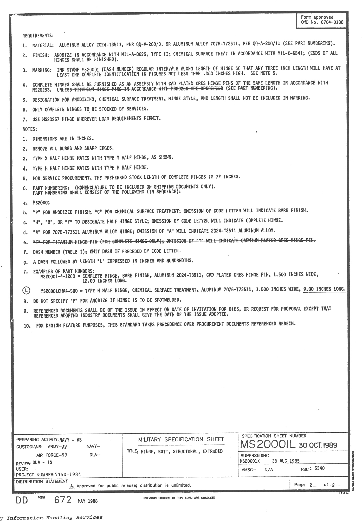
The reamed hinge turned out to be the successful
alternative best meeting the goals of a wear resistant hinge without play. It also has the best strength.
The ‘reamed hinge’ is a piece of stock MS20001 hinge that
is reamed with a .0955 chucking reamer.
The hinge pin is 3/32”, 308L stainless steel welding rod. The welding rod is nominally .09375”. In used hinge material, the rod may fit
without reaming. This however indicates
that there could already be some internal wear. It is best to start with new hinge
material. Even with new hinge material,
not much metal is removed. The reaming
generally only removes material near the entrance and exit of each hinge
element. The result is a very clean
fit. This good fit has both eliminated
the relative movement and wear observed previously on the stock MS hinges. It has now been several years since I
switching out all of my hinges.
This following clip shows a reamed hinge after about 10
years of use and 850 hour of flight time as an aileron hinge on the Lancair
360. I clean, lube the hinges with LPS2
at each annual condition inspection.
Thus far, it looks like they will last the life of the airframe.
850 hour Reamed Hinge TIS Video
Teflon Sleeved
Hinge Pin
The other two alternatives, Teflon sleeves and Carbinge,
fell short in a few areas. This was
primarily due to the non-metallic bearing material in each. The Teflon Sleeve kit was actually installed
on my plane for about a year. Piano
hinges act much like shears when under load. Teflon has very low strength (1500-3000
psi) and is relatively soft. The highly
loaded flap hinges nearly cut all the way through the Teflon sleeve. As this was occurring over time, the flaps
rode ever higher, until finally making contact with the upper wing skin. Even when new, the
Teflon sleeve approach had the worst dimensional control of all the
options.
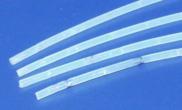
Figure 2, Damaged Teflon Tubing (Inner Flap hinge tubing
could not be removed)
Carbinge
Carbinge was another alternative examined. The stock hinge, as supplied, had more play
then desired. While one can use a better
fitting third party pin, a few other undesirable characteristics remained. First Nylon is subject to creep. That is, under load, it will slowly flow.
Technical Data regarding Nylon creep can be obtained from “International
Plastics Handbook,
Hanser”. I
tested this characteristic by loading a sample of Carbinge for one month. When the load was removed, there was
increased play in the direction the load had been applied. The pin was slowly pushing through the
Nylon.
Nylon is also hydroscopic.
It will absorb moisture and swell when exposed to high humidity. The magnitude of the dimensional change needs
to be considered in design. In this case
it was equal to the total clearance I wanted to achieve. Therefore, dimensional stability could not be
sufficiently controlled.
The primary drawback was that, Nylon has very low stiffness
when compared to metals. Aluminum is ~
10,000,000 psi. Nylon starts at
~400,000, but drops sharply with humidity. In Carbinge, Nylon replaces aluminum
as the bearing material. This
dramatically lowers the stiffness of the hinge.
In other words, for the same load, Carbinge has much greater deflection. The following video compares deflection of
Carbinge and aluminum. Even with five
times the load, the aluminum has far less deflection.
Finally the strength of Carbinge was far below that of the
aluminum reamed hinge. The following
clip shows the results of a simultaneous pull test of Carbinge and reamed
MS20001 hinge material. The test showed
that caution is called for when considering Carbinge in high load
applications. Here one can also see the
difference in stiffness (deformation) during the load application.
Pull Test, Carbinge vs. MS 20001 Video
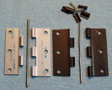
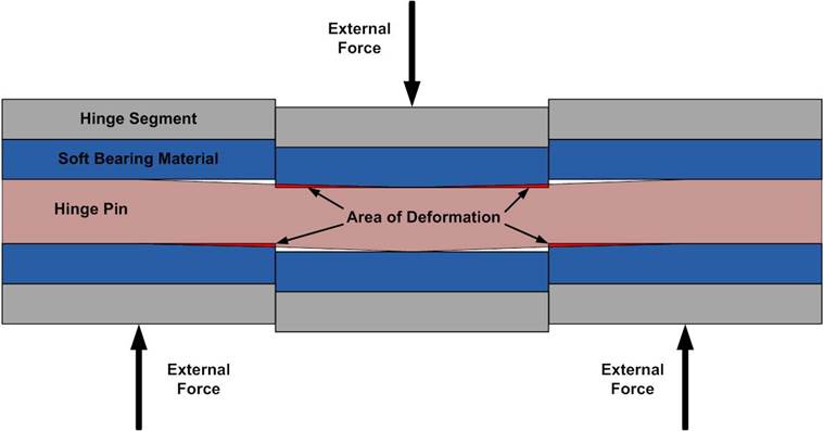
Figure 3, Hinge Sections after Pull Test
Note
the S-shape of the Carbinge pin after the pull test. This is a by-product of the soft bearing material.
Since the pin is not infinitely stiff and the
Nylon cannot sufficiently support the hinge pin, the forces will try to bend
the pin into a slalom S-shape. The
figure below illustrates this deformation.
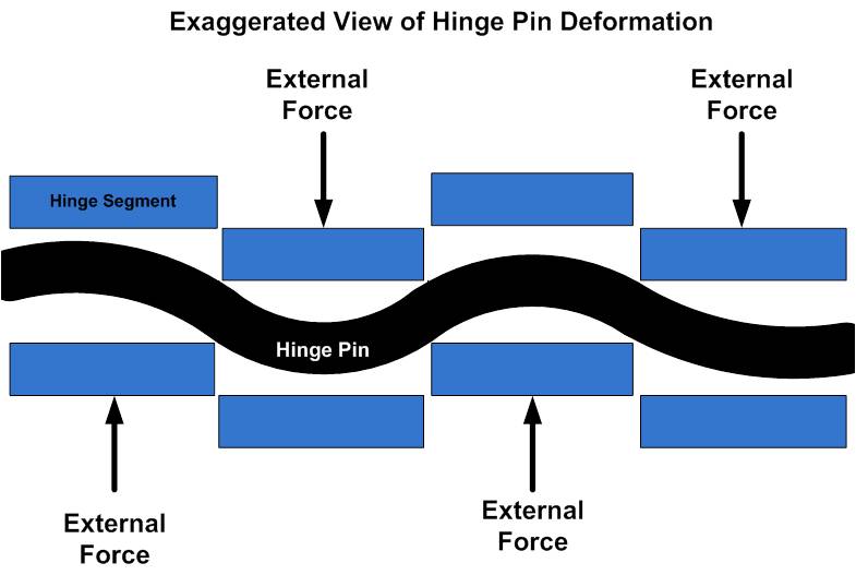
The deformation of the pin serves
to concentrate the loading at the very edges of each hinge
segment. If the hinge material is not able to withstand this local
stress it will begin to deform. Thermoplastic bearing materials are
particularly susceptible to this load concentration allowing a greater
deformation. This, in turn, exaggerates the S-shape of the hinge
pin. The net effect, even for light to
moderate loads, is relative hinge movement, even with the best pin to bearing
material fit at installation.
The following clip shows what appears to be
a loose fitting hinge pin. In fact, the
pin was a snug press fit. The yielding
of the Nylon results in a lot of movement even with this relatively mild load
of 10-15 lb/in.
Carbinge
Press-Fit Pin Movement Video
The
search for a precision hinge with high load bearing capability led back to all
metal construction. Along with a larger
pin, reaming improved the tolerance and strength of the final hinge
assembly. This produced a precision fit
that eliminated the wear seen earlier.
The best part is that the solution was easy and inexpensive to implement.
2014
Update
Straightened
stainless steel wire of all sizes has become more available in recent
years. This provides the opportunity to
use a pin diameter larger than the 3/32” welding wire described above. Since 2011, I have been testing a section of
hinge material reamed to .098”, the maximum permissible in the manufacturing
tolerance paired with a pin of .096 +.001/-.000. This approach provides a guarantee of a
tightly controlled fit even if a batch of hinge material is used that falls on
the upper end of the tolerance band.
Reaming to 0.098” will generally remove much more material and requires
more time to ream the hinge material.