Not Just Effective, But Efficient Engine Cooling
What works and what doesn’t work in aircraft engine cooling is very difficult to quantify. There are simply too many variables to clearly establish cause and effect without expensive and time consuming testing. Overlooking just one little, yet critical, detail can make an otherwise good set-up perform poorly.
For a number of years I had contemplated a redesign of the cooling system on N91CZ. I didn’t actually start working on the new system until early 2004. Waiting this long did give me the opportunity to gather a lot of temperature data on the original system. The following files, reports and photos document the changes and the accompanying performance gains. Dropping CHTs by 30 degrees while increasing airspeed 5 kts, made this project well worth the effort.
Cooling Report in pdf format, current version of report that follows below.
Efficiency Improvements for the Lancair 360
by Chris Zavatson
rev. 8-10-2005
I finished building and started flying my Lancair 360 in 1997. While I had made a number of minor modifications during construction, these were all geared towards ease of long term maintenance and did not involve performance of the plane. The firewall forward was pretty much a stock set-up assembled with Lancair supplied components. I had installed a factory new, totally unmodified O-360AIA, and the standard Hartzell prop.
The plane was great fun in this original configuration, but after flying a few years I began to consider reworking various items that would improve the performance. The two areas of interest were the induction system and cooling. A little background is in order. Initially I had been cruising at 199 KTAS. At about 400 hours my first engine was totaled by jet fuel contamination. Unfortunately, the replacement engine only propelled me to 196 KTAS. That was both depressing and motivating. It finally got me working seriously on the first of my two major modifications, a new induction system. This modification brought my cruise speed up to 201 KTAS and was described previously in a Lancair Network News article: “Induction System Improvement on the Lancair 360”, 8-21-2000. The cooling system wasn’t tackled until quite a bit later, in 2004. Both projects literally transformed the plane operationally. The combined results of both produced a cruise speed increase of 10 knots down low and 15 knots up high in addition to dramatically cooler engine temperatures. What follows is a description of the more recent modification to the cooling system.
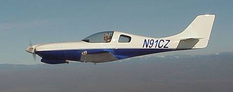
N91CZ with the original cowling
.
The Cooling System
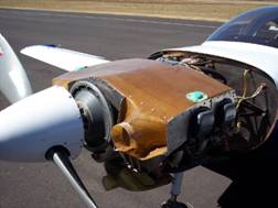
The original cooling system on the plane was typical of most GA aircraft. A flexible baffle seal contacting the top cowl created a plenum chamber above the engine. The inlets were split, half part of the lower cowl and half part of the upper cowl. One noteworthy difference is the size of the inlets. On the typical GA aircraft the inlets are quite a bit larger than is found on the Lancair. The nominal inlet diameter was only 3.5 inches. Once the original cowl was actually assembled the inlets were a bit vertically oblong, just over 4 inches on one side and just under 4 inches on the other. On a plane that is aerodynamically clean like the Lancair, cooling drag becomes a significant percentage of the total drag. Therefore, cooling drag needs to be kept under control to obtain good speed. Reducing the inlet and exit areas is one way of doing this. The result is that many Lancairs tend to run a little warm. Not prohibitively hot, but enough to require monitoring and sometimes operational constraints to keep temperature from getting out of control. I found myself using the mixture control to keep the warmest cylinder under the 400 deg F mark, especially during the warmer months of the year.
There were two main aerodynamic issues in the original design that needed to be addressed. First was the transition from the cowl inlet to the plenum chamber above the engine. This rapid expansion, and the attendant flow separation, was adversely affecting the oil cooler, located in front of the #2 cylinder, at air speeds below 120 KIAS. It was also wasting a lot of energy. I wanted to expand the air flow to the greatest extent possible without separation using a set of diffusers. The second issue was the entire concept of using flexible baffle material to seal in the cooling air. This method of sealing has been shown to be very inefficient. NASA report CR 3405 quantifies the effectiveness of the flexible baffling in a typical installation. The results are quite enlightening. On the test aircraft the volume of cooling air entering the inlets had to be increased 55% to make up for leaks in the system. With the help of some RTV silicone and a hard plenum top 100% sealing was achieved.
At the same time there were a number of non-aerodynamic issues I also wanted to address.
1. The original cowl was so close to the exhaust system, in some areas, that it was not possible to install effective heat shields. As a result, the cowl was slowly showing signs of heat damage.
2. The original landing light tube was made of PVC pipe. It was also showing signs of heat damage where it was not covered by fiberglass.
3. In a few spots between fasteners, along the split line, some bowing had developed. The wall thickness was too thin in these areas and required the use of Tinnerman washers.
4. The original cowl was polyester resin. I wanted to switch to epoxy.
The overall goal was too reduce temperatures without sacrificing speed. The brute force method of increasing the inlet and exit areas was therefore not an option. I really wanted to focus on efficiency of the system. In fact, I was planning on actually reducing the inlet and exit area hoping that efficiency gains would make up for the lost area. If all went well, shrinking this inlet and exit area would produce a drag reduction and a higher airspeed.
All the design details were conceptually worked out before any work on hardware was actually started. There would be a few months of work ahead of me before having to tear into the plane itself. I always make molds for custom fiber glass parts. While there are a number of one-off methods, I prefer to spend the time and effort fabricating real molds. One is rewarded with parts of the best possible quality. Having molds also allows one to try different ply schedules or simply to make additional parts if needed.
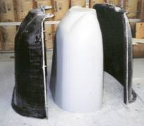
Cowl plug and mold Diffuser
plugs, mold and finished parts
The first piece I started was the plug for the cowling. (A plug is dummy, non-functional version of the part you intend on making. It has the same external dimensions, but may be completely solid and made up of any number of materials such as wood, foam, fiber glass, Bondo etc).
The external design changes to the cowl are not all that noticeable at a distance. The inlets were brought back down to the original 3.5 inch nominal diameter- this time perfectly round. These were moved forward about ¾” and made equidistant to the propeller. The rear of the cowl was shaped to better fit the actual cross section of the fuselage - the original was too large. A key change was the location of the split line. It was routed over the top of the inlets keeping the entire inlet intact and wholly part of the lower cowl. With the top cowl removed, one then has great access for sealing the inlets to the plenum chamber.
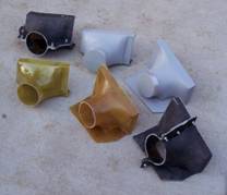
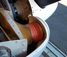
New one piece inlet Diffuser and plenum
chamber
When the first new cowl was fabricated, a few additional changes were incorporated. First, the area of the screw line was made substantially thicker. In addition, to preventing bulging between screws, the greater thickness permits the use of countersunk screws without the use of Tinnerman washers. The overlapping joggle on the lower cowl was formed to the new upper cowl half while still in the mold. The result was a perfectly mated set requiring no fitting except to the fuselage.
After the prototype cowl was hung on the plane, I proceeded with the plugs for the two main diffusers and the plenum top. While the concepts had been worked out earlier, I wanted to set the alignment of the diffuser inlets according to an actual cowl. In order to down-time to a minimum, the original cowl was reinstalled while the diffuser and plenum top molds and parts were being fabricated.
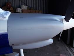
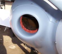
New cowling in primer 4”
SCAT duct seals inlets to diffusers
Once the first set of diffusers and a plenum top were finished, the original cowl was removed for the last time. A few sheet metal pieces up front were replaced with new, so that the original parts could be preserved. The majority of the aluminum baffle pieces did not require any alteration. The new composite components were trimmed and fitted with nut plates for easy removal.
Flight Testing
During flight tests, improvement was immediately apparent. Since these changes were made in July, I was fortunate to have 100+ deg F temperatures at the airport for testing. This gave me the opportunity to test the most stressing conditions the cooling system would ever see. I recorded temperatures in cruise at many different altitudes for comparison with data collected throughout the previous years of flying. Temperatures during take-off, climb and ground operations were also noted. I could not have been more pleased with the new observed temperatures. The hottest cylinder dropped 30 degrees at lower altitudes and 42 deg F up high at 17.500’. The highest observed CHT during take-off dropped 40 deg F. The spread between the cylinders narrowed considerably and is now typically within a 10-15 degree band. The scatter plots of CHT vs EGT show cooling effectiveness in cruise. These points cover a range of altitudes from 5,500 to 17,500’ and OATs from 23 to 88 deg F. In order to determine the precise effect of the new cowling, one could sort through the data to find before-and-after pairs with matching altitude, OAT, and EGT. However, despite the large number of points recorded it is difficult to match these three variables exactly. Even with additional data recording, matching exact points will continue to be difficult since the better cooling allows much higher EGTs to be used for normal operation. Therefore, multiple regression analysis was performed using all the temperature data collected in the last seven years of flying. This made it possible to generate a computer model that predicts all CHTs and EGTs for both the old and new cowls given any altitude, OAT and mixture setting. A side-by-side comparison of the new and old cowl performance for any flight condition is now much easier to perform.
Regression Model Input/Output Sheet
Raw CHT vs EGT Data points in cruise at various
altitudes, OATs comparing original cowl to new design
(curve fit for visual reference only)
Oil cooler performance at low speed also improved. Now the oil cooler is functional all the way down to zero speed. In cruise it cools just as always - 182 deg F most all the time with the occasional excursions to 190 deg F during the middle of the summer.
While the reduced inlet and exit area still allowed for improved cooling it also had a significant effect on drag. I was hoping to see some improvement in cruise speed, but was quite surprised when the increase came in at 5 knots (from 201 to 206 KTAS). The combination of higher cruise speed and drop in temperatures really shows how much energy was being wasted in the original configuration.
Conclusion
Of all the modifications I have made over the years, this was certainly the most extensive in terms of time and effort. On the other hand, it also had the greatest pay-off. The induction system change in 2000 added speed by increasing manifold pressure. The cowl added speed and lowered temperatures solely by improving aerodynamic efficiency. When you extract performance gains through efficiency improvements, it feels like you are getting something for nothing. While the conventional cooling system design is certainly the easiest to implement, it comes at a cost in performance. Fortunately the experimental category allows us to explore other options.
Fly fast and stay cool.
Links:
Cooling System Evaluation, Pressure and Flow measurements
Cooling Report in pdf format, current version of report that follows below.
Summary Information Sheet in pdf format, project summary condensed onto one page.
EXCEL temperature calculator, Multiple regression model that uses temperature data gathered over the last nine years to compare the performance of the old cooling system to the new one for any given flight condition. As an aid to the user, the spreadsheet contains a macro for calculating standard atmosphere temperature at the altitude requested. Your security settings must allow macros to be down loaded for this feature to work. As more flight data is gathered, I periodically update the temperature data base.
NASA report CR3405, very good reading. Real data showing the virtues of the plenum cooling system. It also contains information of inlet design. A long and sometimes technical read, but well worth the effort.
Additional Photos of Installation A number of additional photos of the both the original installation in N91CZ and later installations in other Lancair 360s.